Measuring Bearing Capacity with the Light Weight Deflectometer

Clients are always looking for ways to get a better understanding of the ground conditions at a specific point in time, and how the bearing capacity of a site has altered due to changing conditions, like rain.
Let’s take a crane lift as an example. The insitu ground conditions need to be identified in order for the temporary works platform to be designed. However, immediately prior to the crane lift the insitu conditions are required to be verified. This is to check that the site conditions remain as per the design assumptions – and thus being able to provide real time results from tests that directly model the proposed loading scenario are important.
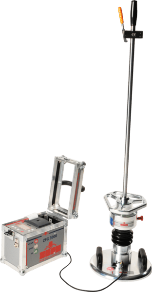
For this article, we describe the Zorn Light Weight Deflectometer (LWD) as an example of equipment suitable of achieving these verification outcomes for the ‘as-encountered’ site conditions.
The LWD used in the standard, calibrated configuration – 10 kg weight, full height drop and 300 mm plate – will provide a single stress vs. deflection datapoint (i.e. deflection magnitude under 100 kPa stress). However, varying the weight mass, plate diameter (and potentially drop height) facilitates the construction of an extended stress vs. deflection dataset, such that the extent of a linear (elastic) response can be determined and the allowable bearing capacity directly identified. 10kg and 15kg drop weights and 300mm and 150mm diameter plates are available.
For example, the following LWD configurations would yield varying test stress for which the deflection would be measured:
- 15 kg drop weight, 300 mm diameter plate – Approx. 150 kPa stress
- 10 kg drop weight, 150 mm diameter plate – Approx. 400 kPa stress
- 10 kg drop weight, 300 mm diameter plate – Approx. 100 kPa stress
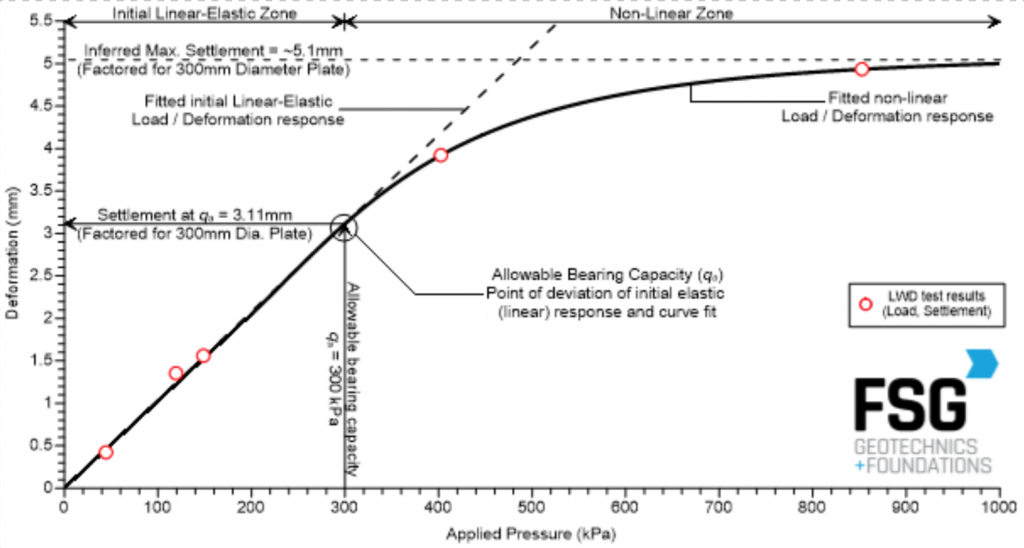
After factoring for the varying plate diameters, the measured deflections would be graphed as deflection vs. test pressure. The allowable bearing capacity is represented by the point of deviation from the initial linear response. If the test stress is of sufficient magnitude, the ultimate bearing capacity may also be able to be identified.
This technique is shown on the below graph – thanks to our friends at FSG Geotechnics + Foundations – which also identifies the demonstrated allowable bearing pressure of the site.
To provide additional data points, the user could also change the drop height within any specific weight / plate diameter configuration of the LWD. For example, the drop height could be split into thirds – one being the calibrated position (full drop height), and the other two are positions temporarily marked upon the drop shaft. Although the Zorn LWD doesn’t have a load cell, you can calculate the approximate applied pressure for each drop height based on the proportionate heights. Complete the LWD test as per the normal test technique and the deflection magnitude will be recorded. These can then be added as (approximate) supplementary stress vs. deflection datapoints to those taken under the calibrated test configurations.
Note the measured deflections are obtained from the LWD – a dynamic, surface-based test – represent the composite arrangement within the limited zone of influence of the test (penetration depth). Assessment and interpretation would still be required in confirming the applicability of the LWD test results to the proposed outrigger dimensions. Similarly, the use of the LWD to directly demonstrate allowable bearing capacity onsite, is a step-change from the Safety Factor method used to estimate the same parameter from other geotechnical test results.
In conclusion, the Light Weight Deflectometer is a useful tool to help directly demonstrate the allowable and ultimate bearing capacity of a site, and monitoring any variation of these values due to changing site conditions throughout the timeframe of project delivery.
I must confess that this equipment is fantastic compared to the old technology.
Since hiring the LWD I have used it on numerous jobs in a wide variety of material types all over WA. The ability to give “real time” test results have worked particularly well for me as i can show my clients numerical values which gives them a direct understanding of some of the benefits using Betta Roads has brought to their road construction projects. The feedback I have been receiving over the last few months has lead me to purchase the LWD and incorporate its use as an integral part of our projects.
I have known the team at Insitutek for over ten years. Their professionalism, positivity and enthusiasm for their work is outstanding and I am pleased to recommend them.
Insitutek Blogs

We find clients are often looking for ways to improve geotechnical testing outcomes and do it more efficiently at the same time. This drives their buying decision making. Australian Soil and Concrete Testing (ASCT) was a case in point when they were searching for Plate Load Test equipment for their upcoming Collector Wind Farm project. Some of the things that motivated them include: […]

We are excited to introduce the addition of a new Liquefaction Risk Estimation module in WebSprint©. Paired with our cutting-edge products, PANDA® and GRIZZLY®, this module enables you to assess the liquefaction risk of soils exposed to seismic stress. PANDA® Instrumented DCP: This cutting-edge tool provides dynamic penetrometer soundings, delivering precise data crucial for seismic risk evaluations. GRIZZLY® […]

The Australian Geomechanics Society is gearing up for a series of geotechnical events across VIC, WA, NSW, and SA-NT. We are thrilled to inform you that we will be sponsoring and attending these exciting geotechnical events, and we would love for you to join us. It’s a fantastic opportunity to catch up, explore our booth (VIC), and stay informed about […]