A Reliable Methodology for the Determination of the Modulus of Subgrade Reaction – Case Study
")
Engineers appear to be fixated on soil bearing capacity as the fundamental soil parameter for foundation design worldwide, with the assumption that the footing will behave as a rigid body. This assumption is usually not applicable for large and multi-column foundations, and in such conditions, engineers prefer flexible analysis using numerous available software. These computer programs often ask for an input parameter known as the “modulus of subgrade reaction”.
The modulus of subgrade reaction, ks (also called coefficient of subgrade reaction or Westergaard Modulus), is defined as the pressure per unit deformation of the subgrade, and it is often expressed as kN/m2/m or kN/m3. Mathematically, the modulus of subgrade reaction (ks) is expressed as:
ks = p/s Eqn 1.
Where p = applied pressure and s = soil settlement
The structural engineer widely uses this modulus in the design of slab foundations, pavements, high-rise buildings, bridge footings, rail infrastructure, over-ground tanks, windfarm foundations, temporary platforms etc. However, a geotechnical engineer is responsible for providing the appropriate subgrade reaction modulus. The appropriate estimation of subgrade reaction modulus would result in the accurate design of structures.
The ks value can be determined by field tests or by correlation with other tests. There is no direct laboratory procedure for determining the ks value.
1.0 Determination of ks
1.1 Empirical Method
Research has shown that ks can be correlated with soil properties; however, these correlations have shown a wide range of ks. For example, Bowles (1996) established a relationship between allowable bearing capacity and modulus of subgrade reaction (ks) per Equation 2.

Where, FS = factor of factor, qa = allowable bearing pressure.
Similarly, Lin et al., (1998) demonstrated that the value of the coefficient of subgrade reaction ks could be estimated per Equation 3.

Where, qa = allowable bearing pressure, δa = allowable settlement
Equations 2 and 3 have shown significant variation in subgrade reaction values in practice.
1.2 The Traditional Plate Load Test Method
A common method of determining ks value of subgrade is the insitu plate load test. This test involves the application of pressure on a steel bearing plate into the ground surface measured with a hydraulic jack and the corresponding surface settlement recorded from dial micrometres on the plate surface, and the modulus of subgrade reaction determined using equation 1.
The traditional plate load test setup is illustrated in Figure 1.
Figure 1: Traditional Plate Load Test Set Up
This traditional plate load test method is plagued with the following:
- The test requires the operator to remain underneath the counter load as it is being jacked into position to take settlement readings of the plate on dial gauges. As work health and safety regulations in workplaces become increasingly strict, operations of this nature will be regarded as a very high-risk job, and stringent permits will soon be required to perform such activities onsite.
- A major setback with the plate load test is the influence of environmental conditions on the process. Experience has shown that plate load test cannot be conducted in windy conditions because the dial micrometres are affected by wind and tends to provide false settlement values and some cases, produces values that correspond to soil heaving.
- The equipment is very cumbersome; hence, it cannot be carried about easily.
- It is time-consuming to set up the dial micrometres and the entire test as a whole. At least three (3) micrometres are set up with two datum bars.
- At times, dial gauge readings are significantly different, indicating that the actual settlement corresponding to an applied load may not reflect true settlement; despite this, the average reading is adopted as the actual settlement of the plate.
- The tendency of an operator to bump on a dial micrometres is very high. The operator works within a confined space and usually lies or kneels underneath the counter load, increasing the likelihood of bumping the setup during the test. Such contacts render the test invalid, and the test have to be repeated.
- The plate load test usually involves two persons. One to take charge of the jacking component and usually stay away from the counter load depending on hose length. The second operator is usually underneath the counter load and remains to take settlement readings of corresponding pressures.
- Data acquired from the field is manually manipulated or put into a spreadsheet to produce the required results. This leads to delays in site activities as results may take a day or two to produce, invariably leading to client cost increases. Additionally, data processing is dependent on the engineer’s experience. However, even the most experienced engineer is subject to human errors (reading some else’s handwriting, typing, spreadsheet calculations); hence designs could be compromised.
- At the end of a test, operators are often covered in dirt/stains. Operators usually sit or knee on the ground or lie face down as they wait for the required time to record the settlement of an applied load.
- There is a greater likelihood of one of the three (3) dial micrometres being out of calibration but still in use. The risk of this happening is three times greater than a system that will require the use of a single electronic gauge.
1.3 AX01 Plate Load Test
To overcome the above limitations, an improved plate load test kit to provide a more reliable, improved safety, and repeatable test, known as the AX01 Plate Load Test, was used by Qualtest to investigate the modulus of subgrade reaction for a client. This instrumented Plate Load Test AX01 meets the DIN 18134 and ASTM 1195 / ASTM 1196 standards.
The AX01 Plate Load Test is an automated system that eliminates the intricacies of the traditional plate load test equipment and is a one person operation. The technology enables the acquisition of field data by electrical means, including data processing and presentation of results, hence eliminating human error.
Qualtest used their AX01 Plate Load Test equipment to determine the modulus of subgrade reaction for their client in Murrumba Downs, Queensland. In this test, compressive stress was applied to the soil layer through a 300mm diameter rigid plate, and the deflections were measured for different values of stress electronically.
The plate load test permits the relationship between load and settlement (load-settlement curve) to be determined.
The instrumented plate load test equipment, AX01 Plate Load Test, used for the Investigation is shown in Figure 2.
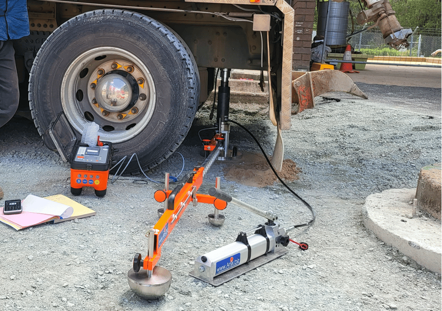
The electronic plate bearing tester AX01 is designed to determine load-settlement curves of soils and sub-bases. The obtained load-settlement curves enable the user to evaluate the deformability and load-bearing capacity of the soils.
The electronics of the AX01 automatically calculated and reported the modulus of subgrade reaction at the tested locations.
The determination of the ultimate and allowable bearing pressure of soils using the automated AX01 Plate Load Test is another topic for another day.
Special thanks to Dennis Alazigha, Principal Geotechnical Engineer, Qualtest for technical input.
I have known the team at Insitutek for over ten years. Their professionalism, positivity and enthusiasm for their work is outstanding and I am pleased to recommend them.
The Light Weight Deflectometer (LWD) was first used in 1998 by the Minnesota Department of Transportation (Mn/DOT) at the Minnesota Road Research Project. Starting in 2005 the LWD has been used by Mn/DOT as an acceptance tool for the compaction of roadbed and miscellaneous embankment and trench construction, culvert treatments and other tapered construction.
We have been very happy with the support from Insitutek. They are knowledgeable and have been super responsive and flexible to our needs.
Insitutek Blogs

We find clients are often looking for ways to improve geotechnical testing outcomes and do it more efficiently at the same time. This drives their buying decision making. Australian Soil and Concrete Testing (ASCT) was a case in point when they were searching for Plate Load Test equipment for their upcoming Collector Wind Farm project. Some of the things that motivated them include: […]

We are excited to introduce the addition of a new Liquefaction Risk Estimation module in WebSprint©. Paired with our cutting-edge products, PANDA® and GRIZZLY®, this module enables you to assess the liquefaction risk of soils exposed to seismic stress. PANDA® Instrumented DCP: This cutting-edge tool provides dynamic penetrometer soundings, delivering precise data crucial for seismic risk evaluations. GRIZZLY® […]

The Australian Geomechanics Society is gearing up for a series of geotechnical events across VIC, WA, NSW, and SA-NT. We are thrilled to inform you that we will be sponsoring and attending these exciting geotechnical events, and we would love for you to join us. It’s a fantastic opportunity to catch up, explore our booth (VIC), and stay informed about […]