Tie Bar Alignment – Concrete

Overview

  • Non-destructive
  • Accurate measurement of dowel bar or tie bar positions and alignment for concrete pavements
  • Horizontal and vertical misalignments with accuracy of ±4 mm and side shifts with accuracy of ± 8 mm
  • Meets ASTM E3013 standard

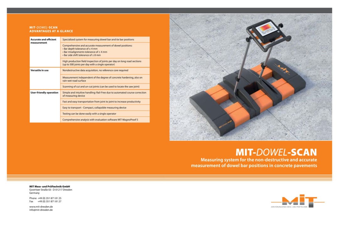
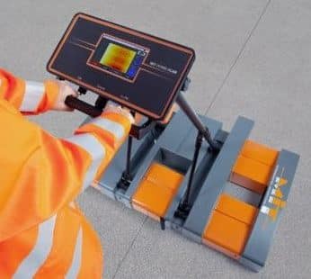
The MIT-DOWEL-SCAN enables the accurate measurement of tie bar / dowel bar position and alignment in concrete pavements.

The equipment is designed with the accuracy required for dowel bars but most clients use it for both dowel bars and tie bars.
Advantages

The advantages include:

  • Positioning and alignment can be checked as soon as a person can walk on it after concrete placement
  • As the results are immediately available, it allows the contractor to take corrective action immediately, making adjustments during the paving process
  • Non-destructive test (NDT) – no need to do coring to measure depth
  • One person operation
  • Measurement can be taken extremely quickly (less than one minute per joint across several lanes)
  • Results are immediately seen on a graphical display on the screen for quality control purposes
  • Embedment depths, misalignments & translations are determined precisely, even on rain-drenched surfaces
  • Under normal conditions, depths as well as horizontal and vertical misalignments can be determined with an accuracy of ±4 mm and side shifts with an accuracy of ± 8 mm
  • Used to evaluate new and existing joints.
  • Basket joints can be evaluated if the shipping wires are cut.

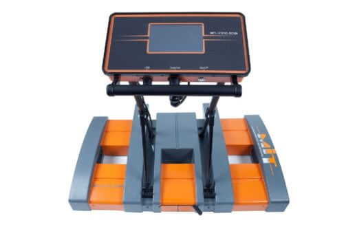
The MIT-DOWEL-SCAN from MIT Mess- und Prüftechnik GmbH adheres to ASTM E3013 and is delivered as a complete system ready to use. The measuring vehicle is equipped with an operating unit, a laser unit, MagnoProof software package, manuals and a solid transportation case.
Applications

Concrete pavement applications include:

  • Quality Control by contractors for checking their installation process
  • Highway construction of plain concrete pavements
  • Quality Assurance by owners for accepting completed facilities
  • Plain concrete runways, taxiways & ramps at airports
  • Concrete Sea Container storage & staging areas in port facilities
  • Forensic investigations of failing joints in existing concrete pavements

Why is Alignment and Positioning Important?

Dowel Bars

Properly aligned and embedded dowel bars are vital in jointed plain concrete pavements. Dowel bars are round, smooth, epoxy coated steel bars placed mid‐depth across transverse joints. They allow load transfer whilst allowing the joint to open and they reduce or eliminate faulting and corner cracks. Significantly misaligned dowel bars may lead to joint locking which can cause slabs to crack. Improper placement (embedment) of dowel bars leads to decrease in load transfer efficiency, which can result in faulting and other pavement distresses.

Tie Bars

Tie bars are deformed, epoxy coated steel bars, typically placed mid‐depth across longitudinal joints or between an edge joint and a curb or shoulder. They are designed to prevent lane separation and differential deflection and reduces transverse cracks by holding the faces of abutting slabs in contact. Although they may provide some minimal amount of load transfer, they are not designed to act as load transfer devices and should not be used as such.

Joints

Joints in concrete pavements of highways, airport runways and container areas are exposed to stresses and strains due to traffic and temperature variation. Steel dowel bars, reinforcement bars and tie bars are built into joints, to support the transfer of loads across the joints and to maintain the elevation of adjacent slabs at the joints. The MIT-DOWEL-SCAN is used to determine the number of dowels and tie bars as well as their accurate positions and tolerable displacements, to ensure the long-term performance of the joints.

MIT-DOWEL-SCAN Calibration, Service and Spare Parts

Insitutek are proud to represent MIT Mess- und Prüftechnik MIT-DOWEL-SCAN in Australia, New Zealand and the Pacific Islands and provide a high level of client support.

We offer a complete spectrum of services including after-sale technical support, servicing, repairs, and calibrations.

To find out more, Contact Us.

How it Works

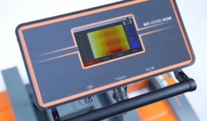
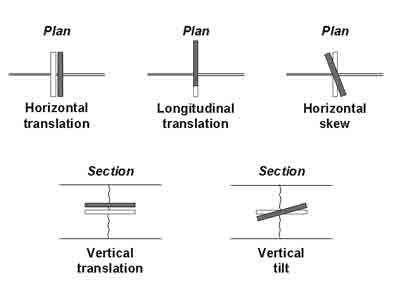
MIT-DOWEL-SCAN Tie Bar Alignment & Positioning Test Data Collector Intregrated onto ScannerThe operating principle behind the MIT-DOWEL-SCAN is pulse-induction. The pulse induction method utilizes the magnetic properties of tie bars to create a magnetic field and is referred to as Magnetic Imaging Tomography (MIT). The equipment emits a weak, pulsating, magnetic signal and detects the transient magnetic response signal induced in the metal bars. The response signals are measured with high precision using special receivers in the testing device, permitting the determination of horizontal misalignment, vertical misalignment, side shift and depth of the dowel bar from the top of the pavement.
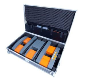
MIT-DOWEL-SCAN Tie Bar Alignment & Positioning Test Entire System fits in Transport CaseThe MIT-DOWEL-SCAN has 10 sensors and a laser to guide the unit along the joint with great accuracy & repeatability. Results are available directly after the measurement on the screen of the device. Data is visualized as a measuring curve and a colorful map in addition to bar positions and misalignment parameters that are computed. A more detailed analysis of the data can be done by the software MagnoProof on a laptop.


Analysis software MagnoProof

MIT-MagnoProof analysis software is part of the MIT-DOWEL-SCAN system for further analysis of the measurement data on the laptop. The MagnoProof software functions include:

  1. Data transfer to laptop / desktop PC via USB
  2. Data organization into work folders for multiple project capability
  3. Software automatically corrects erroneous data
  4. Identifies potential causes of result interferences
  5. Automatic evaluation of depth, alignment, & translations of tie bar / dowel bar positions
  6. Quantative results & Joint map are shown on a single screen
  7. Reports as MS-Excel and PDF files
  8. Joint map integrated into the MS-Excel spreadsheet
  9. Batch processing of multiple joints with statistical analysis tables for each bar per joint

Learn more about the MagnoProof Software for the analysis of dowel and tie bar positions for DBI-inserted bars and dowels in baskets.

Product How it Works Feature TitleProduct How it Works Feature Image

Videos

Tie Bar / Dowel Bar Alignment for Concrete Pavements – MIT-DOWEL-SCAN

Documents

Category

Topic

Publication Date

Guidelines for Dowel Alignment in Concrete Pavements nchrp_rpt_637appendixA

Author: Kyle Hoegh, Lev Khazanovich

Date: February 2009

This Appendix contains information related to:

  • Dowel placement in concrete pavements to identify:
    • problems with alignment,
    • extent of misalignment,
    • methods for determining misalignment, and
    • effect of misalignment on performance;
  • Factors contributing to dowel bar misalignment;
  • Available approaches for estimating the effects of misalignment on pavement performance.

Preliminary Findings from VDOT Demo on Dowel Alignment Using MIT-SCAN2-BT VDOT Concrete Conference

Author: Mohamed Elfino, P.E., Ph.D., Shabbir Hossain, P.E., Ph.D.

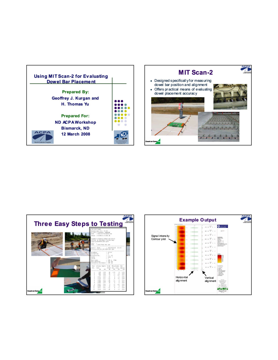
ND ACPA 08 MIT-SCAN2-BT Testing Presentation

Author: George J. Kurgan, H. Thomas Yu

Date: 12 March 2008

EVALUATION OF THE MIT SCAN2-BT ON MN DOT’S 15 INCH LONG DOWELS

Date: June 2009

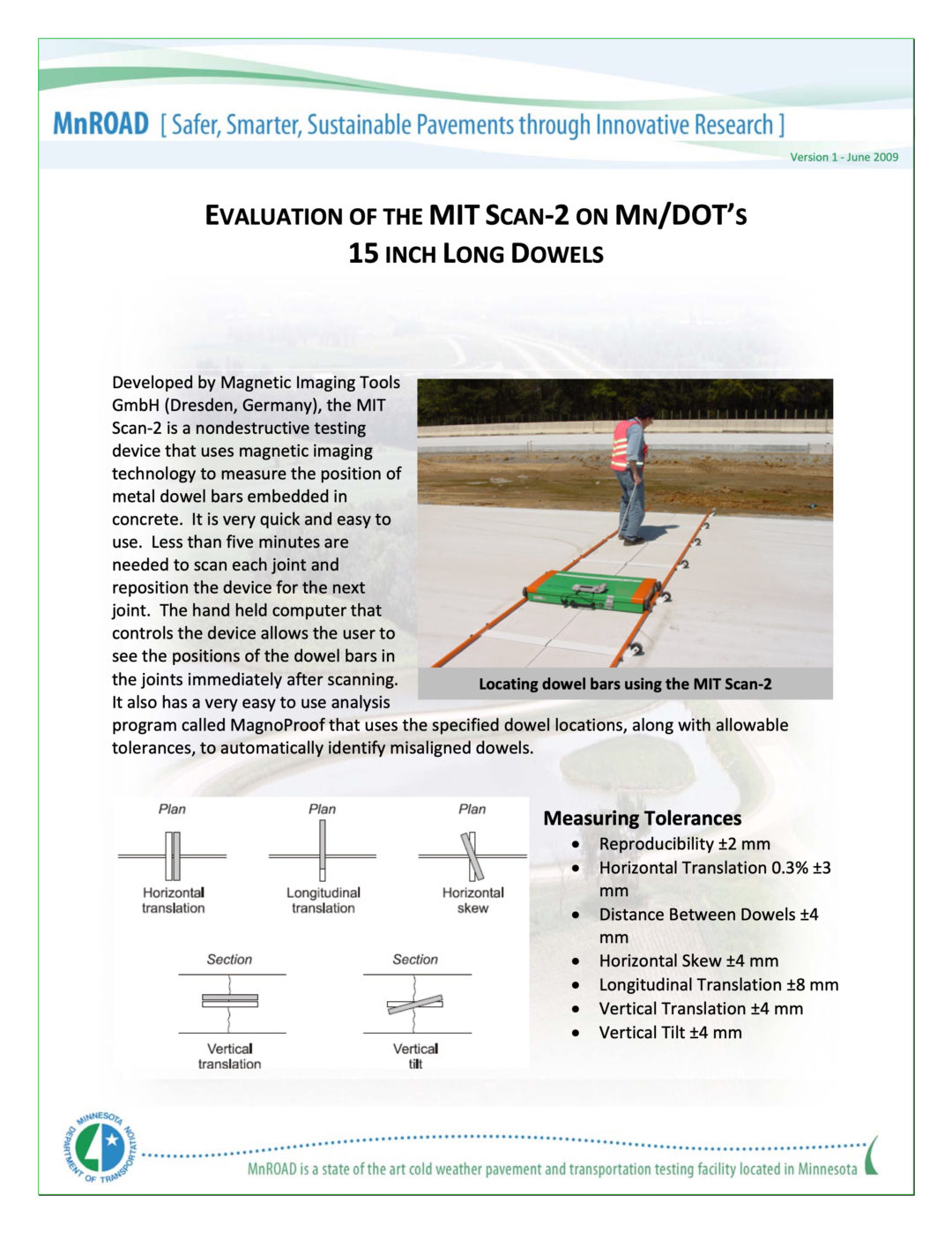
Developed by Magnetic Imaging Tools GmbH (Dresden, Germany), the MIT Scan‐2 is a nondestructive testing device that uses magnetic imaging technology to measure the position of metal dowel bars embedded in concrete. It is very quick and easy to use. Less than five minutes are needed to scan each joint and reposition the device for the next joint.

The hand held computer that controls the device allows the user to see the positions of the dowel bars in the joints immediately after scanning. It also has a very easy to use analysis program called MagnoProof that uses the specified dowel locations, along with allowable tolerances, to automatically identify misaligned dowels.

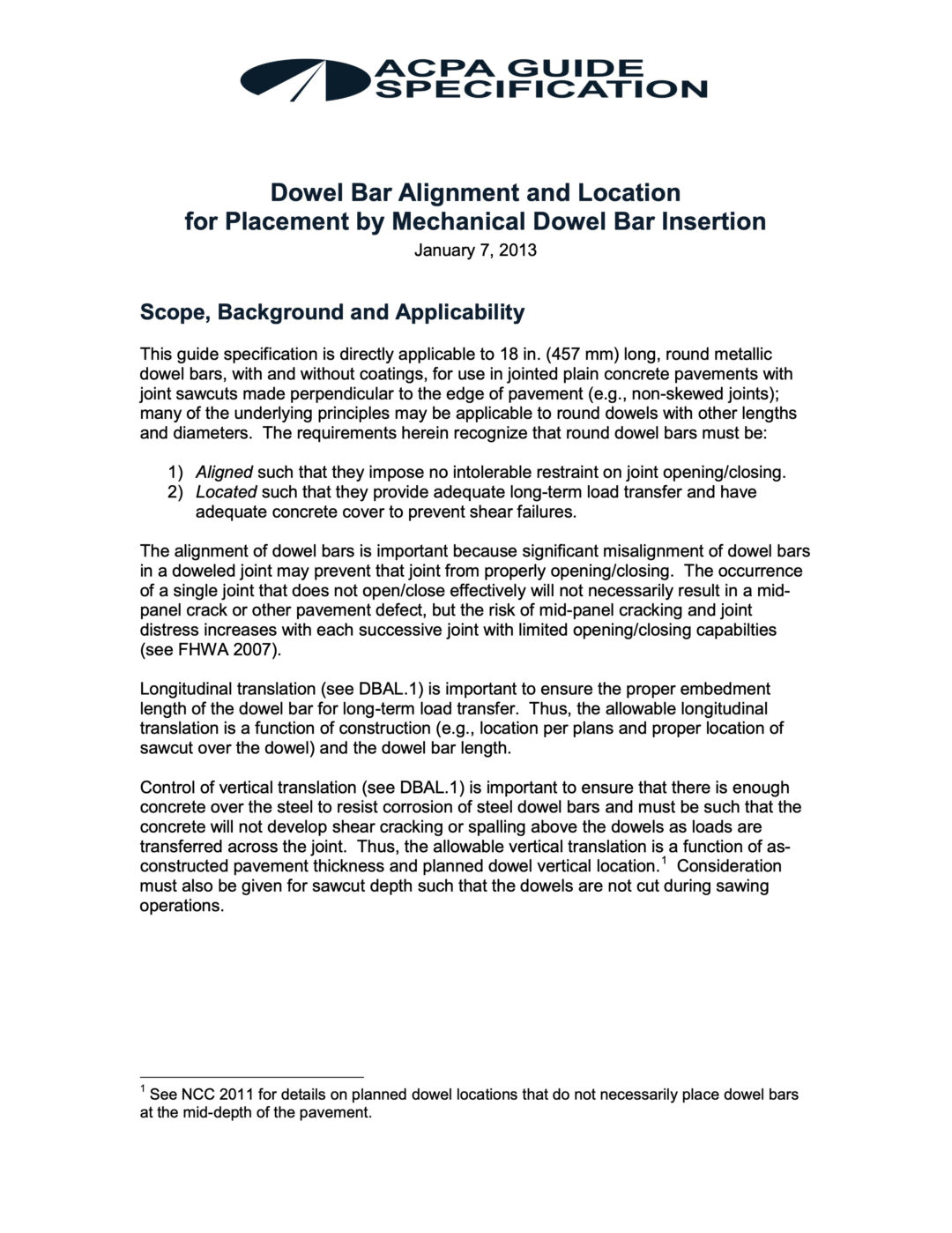
ACPA Dowel Bar Alignment Guide Specification – Jan 2014

Date: 7 January 2013

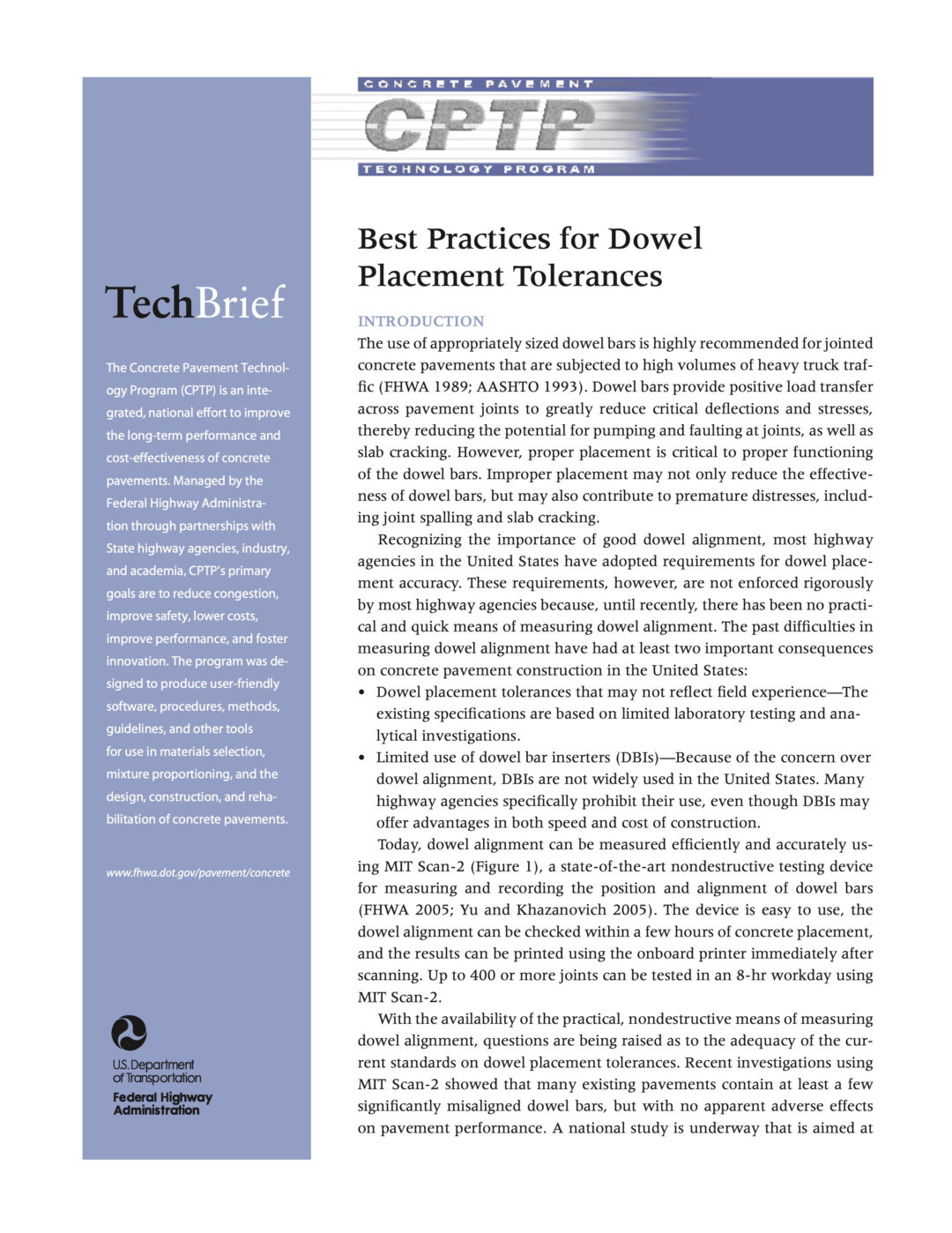
Concrete Pavement Technology Program Best Practices for Dowel Placement Tolerances

Date: January 2007

Dowel alignment can be measured efficiently and accurately using MIT Scan-2, a state-of-the-art nondestructive testing device for measuring and recording the position and alignment of dowel bars (FHWA 2005; Yu and Khazanovich 2005). The device is easy to use, the dowel alignment can be checked within a few hours of concrete placement, and the results can be printed using the onboard printer immediately after scanning. Up to 400 or more joints can be tested in an 8-hr workday using MIT Scan-2.

Evaluation of Dowel Bar Inserter Practices in PCC Pavements using Magnetic Tomography Technology – Farshad Fallah & Yong-Rak Kim – University of Nebraska / Nebraska DOT – Dec 2016

Author: Farshad Fallah, Yong-Rak Kim

Date: December 2016

Improper placement of dowel bars can lead to reduced load transfer between slabs, which results in pavement distresses such as faulting and spalling at joints.

To determine the accuracy of dowel placement by Dowel Bar Inserter (DBI), the Nebraska Department of Roads has used an MIT Scan-2 device to scan the joints in projects where a DBI was used. This device uses a nondestructive magnetic imaging technique to capture the position of dowel bars inside the pavement. The aim of the this project is to analyze the MIT Scan-2 data of the joints constructed using a DBI, and to compare them with the corresponding field performance data. This will allow us to judge if DBI is a reliable alternative for dowel placement, and to improve Nebraska’s current specifications for dowel placement tolerances.

To meet the objectives, the MIT Scan-2 data of scanned joints were initially compared with dowel placement specifications suggested by national agencies. It was observed that the longitudinal translation and rotation of dowels in a portion of scanned joints fell outside recommended tolerances. The longitudinal and vertical translation of the dowels were respectively higher and lower than the average values reported by a similar study (Khazanovich et al. 2009). MIT Scan-2 data and field performance data were then compared to find any linkage between pavement distresses and dowel misalignment levels, enabling us to potentially improve Nebraska’s current specifications as well as conclude if any of the distresses were caused by low placement accuracy of the DBI. No linkage was found between pavement performance and dowel misalignment levels for over 220 joints that were investigated in this study. No transverse cracking was observed during field investigation, and the spalling at joints was likely to be the result of joint saw-cut operations. However, measured distress from joints with missing or completely shifted dowels show that high severity dowel misalignment has an adverse effect on joint performance.

Evaluation of Longitudional Joint Tie Bar System CDOT-2011-12

Author: Jagannath Mallela, Alex Gotlif, Paul Littleton, Suri Sadasivam, Michael I. Darter

Date: September 2011

An adequate longitudinal joint tie bar system is essential in the overall performance of concrete pavement. If designed and installed properly, tie bars prevent the joints from opening and consequently improve load transfer efficiency between slabs and between slabs and shoulders, resulting in increased load carrying capacity.

This study evaluated the longitudinal joint tie bar system currently used by CDOT, examining the criteria for proper use of tie bars and determining the maximum number of lanes that can be tied together without negatively impacting the concrete pavement structure. An improved mechanistic-empirical tie bar design method was developed.

Field studies were conducted to investigate longitudinal joint performance and further evaluate the impact of factors related to design and construction practices. The experimental plan for this round of testing included the evaluation of tie bar alignment, measurement of joint load transfer, and measurement of relative slab movement at the joints. In addition, CDOT’s current specifications and practices related to longitudinal joint construction and tie bar design and placement were compared with those of other state agencies.

Field testing results revealed that the measured joint openings at some tied longitudinal joints were in the typical range of non-tied slabs, implying that some tied joints performed as poorly as non-tied slabs. The results indicate the possibility of tie bar failure due to loss of concrete-steel bonding or yielding of tie bar steel. Another key finding was the possible impact of tie bar misalignment or misplacement on poor longitudinal joint performance. Testing indicated that the measured joint openings were wider when the tie bars did not connect to the other side of the joint, or when the embedment lengths were inadequate. On the other hand, tie bars with adequate embedment length on both sides of the joint, even when misaligned, appear to hold the joint tight.

VDOT Field Demonstration of Magnetic Tomography Technology for Determination of Dowel Bar Position in Concrete Pavement

Author: Shabbir Hossain, Ph.D., P.E., and Mohamed K. Elfino, Ph.D., P.E.

Date: June 2006

The purpose of this study was to demonstrate and evaluate the use of magnetic tomography technology through the use of Magnetic Imaging Tools’ (MIT) MIT Scan-2. The main objective was to measure the alignment of dowel bars in a few jointed plain concrete pavements in Virginia and demonstrate the applicability of the technology. The MIT Scan-2 was obtained on loan from the Concrete Pavement Technology Program. This program is managed by the Federal Highway Administration (FHWA) through a partnership with state highway agencies, industry, and academia.

Dowel alignment measurements were successfully performed on both mechanically inserted dowel bars and bars on dowel baskets. Although the verification with field coring showed reasonably accurate measurements, signal interference from uncut dowel baskets, the presence of foreign metal in nearby locations, and bars deeper than 8 in can result in unreliable quantitative results. The repeatability of the measurements for bars on dowel baskets showed general agreement with the data reported from FHWA. The device was found to be user-friendly, and its field operation was simple. Thus, there is a potential benefit from using the MIT Scan-2 as a quality assurance tool for detecting dowel bar misalignment in jointed plain concrete pavement in Virginia.

Brochures

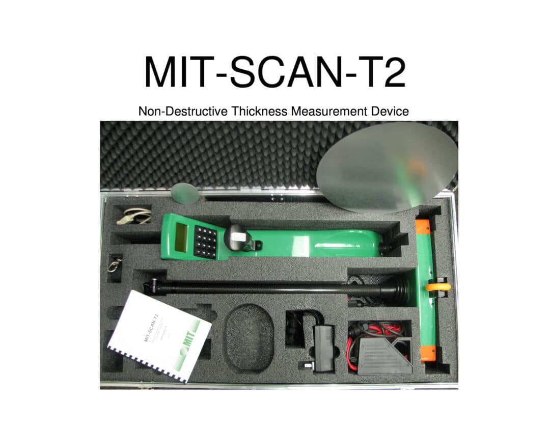
MIT-SCAN-T2 Summary Presentation

MIT-DOWEL-SCAN Tie Bar and Dowel Bar Alignment & Positioning for Concrete Pavements Brochure

Credentials

Credentials for MIT-DOWEL-SCAN

The MIT-DOWEL-SCAN Tie Bar / Dowel Bar Alignment & Positioning Test is used by organisations in the following categories:

  • Road Construction companies
  • Geotechnical Testing specialists
  • Road and Transport Authorities
  • Universities and Research Institutions

To find out more, Contact Us.

The MIT-DOWEL-SCAN is manufactured in Germany by MIT Mess- und Prüftechnik GmbH. MIT stands for Magnetic Imaging Tools. The MIT-SCAN product range has been in production since 2005 and the MIT-DOWEL-SCAN supersedes the MIT-SCAN2-BT.

MIT Mess- und Prüftechnik GmbH
Gostritzer Str. 61-63, D-01217 Dresden, Germany 
www.mit-dresden.de

Trusted by our clients

Select Plant Hire (Laing O'Rourke)
WANT Geotechnics
Wakefield Regional Council
CMW Geosciences
LBS Engineering
Protest Engineering
Red Earth Engineering
WSP Australia
Boom Logistics
Global Engineering & Construction
MPC Kinetic
South 32
Future Generations
Senversa
RJE Global
Macquarie Geotechnical
Life of Mine Engineering
Kleinfelder
Jacobs
Geo Environmental Solutions
ENGEO
Contract Power Group
Bland Shire Council
Betta Roads
Arcos Group
SMS Geotechnical
Aurecon
ADE Consulting Group
Australian Rail Track Corporation Ltd
Plateway Pty Ltd
Butler Partners Pty Ltd
4D Geotechnics Pty Ltd
AMB Geotech SQS Pty Ltd
ATC Williams Pty Ltd
Australian Geotechnical Testing
Australian Soil and Concrete Testing Pty Ltd
BHP Nickel West
Black Insitu Testing
Bloxam Burnett & Olliver Ltd
CMT Engineers
Consolidated Power Projects Australia
CQUniversity Australia
D&N Geotechnical
Dynamic Compaction Solutions
ETS Geo
Evolution Mining: Northparkes
Finnish Overseas Consultants Ltd
Galt Geotechnics Pty Ltd
Geolab
Geotech International
Geotechnical Testing Services Pty Ltd
HEB Constructions
Hunter Civilab
Keller Pty Ltd
KMK Geotechnics
Local Geotechnics
Mitchell Water Australia
Ora Banda Mining
Pardo Engineering
Pearce Geotechnical
Powerlink
Qualtest Laboratory Pty Ltd
Queensland University of Technology
Te Ahu a Turanga Alliance _ Fulton Hogan
Transport for NSW - Sydney Trains
Trilab
Western Geotechnical & Laboratory Services
A&Y Associates
Agincourt Resources
Altissimo Consulting
Canterbury Geotest
Chadwick Geotechnics
Civil Consult
Civil Geotechnical Consultants
Civil Innovation
CivilPlus Constructions Pty Ltd
Civiltest Pty Ltd
Colas Australia Group
Conetec
Construction Sciences
Core Consultants
CPB Contractors
Creative Plumbing
Crozier Geotechnical Consultants
Department of Defence
Department of Transport and Main Roads QLD
Douglas Partners Pty Ltd
Downer Group
First Solar
Fletcher
Fortescue Metals Group
FSG Geotechnics
Fulton Hogan
Gamble Excavations
Gascoyne Gateway
GeoSmart Solutions
GHD
Global Synthetics
Ground Science Pty Ltd

Our Valued Partners:

Insitutek Blogs

On 2 August 2024, geomechanics professionals gathered in Canberra for the Australian Geomechanics Society ACT Insitu Testing Practical Workshop. The event focused on practical demonstrations of key insitu testing methods, including Cone Penetration Testing (CPT), Static Plate Load Test (PLT), Dynamic Probing Super Heavy (DPSH), Light Weight […]

Have you ever wished your Plate Load Test equipment would operate itself? Then our static plate load test with automatically operating battery hydraulic pump is definitely something for you. 🙂 Typically, a hydraulic hand pump is used to apply 15 to 20 load increments over two loading cycles by the operator. One test lasts 20-30 […]

We want to share details of a practical AGS Insitu Testing workshop on 2 August, share something for those working on slope stability and for those in land development and tip you off on getting early bird prices for a couple of up-coming conferences in Australia. If you are interested in modern insitu testing methods […]