MIT-SCAN-T3 Asphalt & Concrete Thickness Test

Overview

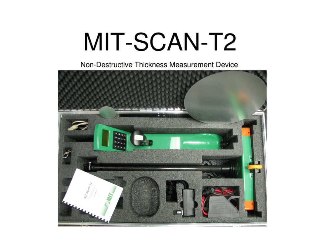
MIT SCAN-T3 Asphalt and Concrete Thickness Test

  • Non-destructive test (NDT) for asphalt thickness and concrete thickness for pavements
  • Full depth or layer by layer thickness measurement for asphalt, concrete and unbound material
  • Accuracy of the MIT SCAN is ± (0.5% of measured thickness + 1mm).
  • Meets ASTM E3209 / E3209M – 20 and EN 12697-36:2003 (Hot Mix Asphalt – HMA) standard

Applications

The consistent application of a required depth of concrete, asphalt or unbound material for pavements is important to road construction contractors and their clients, the road authorities and councils who need to verify that the asphalt or concrete has been laid to the required pavement thickness. The MIT-SCAN-T3 enables you to perform this task efficiently.

This test is only suitable for construction where reflectors can be inserted into the pavement.

The MIT SCAN-T3 can be used directly after the application and rolling of hot asphalt. This means that it can be used to measure partial layer thickness to ascertain exactly how much material is required to bring the pavement thickness up to the final required level. It can also be used on milled surfaces.

The MIT-SCAN-T3 can also be used immediately after concrete has been laid. As soon as you can walk on the concrete, you can measure the concrete thickness.

The MIT-SCAN-T3 from MIT Mess- und Prüftechnik using Magnetic Imaging Tomography technique (MIT), a technique which uses reflectors inserted into the pavement during construction, according to ASTM E3209 / E3209M – 20 and EN 12697-36:2003 (Hot Mix Asphalt – HMA).

Advantages

The accuracy of the MIT SCAN of ± (0.5% of measured thickness + 1mm) compares favourably with surveying or coring. The equipment compensates for changing environmental conditions. This includes wet road surfaces or magnetic aggregates.

Other advantages of the MIT-SCAN-T3 include:

  • Non-destructive measurement (NDT) so reduces or eliminates coring
  • GPS-System to immediately determine and record your position integrated with Google Maps
  • Fast and repeatable
  • Easy data management for storage, presentation and geo-positioning using the PC-based software
  • Light, hand held device, take-apart for transport
  • No impact from wet road surfaces or magnetic aggregates
  • Common reflectors allow measurements from 15mm up to 500 depths
  • Only rough location of reflectors required before measurement
  • Measurements possible on steel reinforced bridges
  • Calibration for customer specific reflectors possible
  • Can be integrated into automatic reflector laying and thickness measurement systems

Here you will find more detail about how the equipment works in practice.

MIT-SCAN-T3 Calibration, Service and Spare Parts

Insitutek are proud to represent MIT Mess- und Prüftechnik MIT-SCAN-T3 in Australia, New Zealand and the Pacific Islands and provide a high level of client support.

We offer a complete spectrum of services including after-sale technical support, servicing, repairs, and calibrations.

To find out more, Contact Us.

How it Works

The MIT-SCAN-T3 is used for both concrete thickness and asphalt thickness pavement applications.

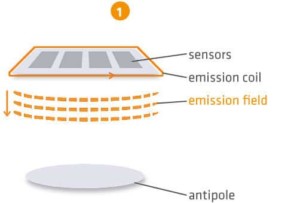
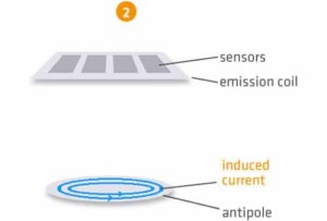
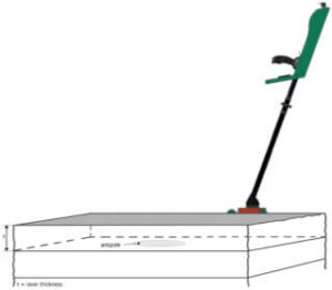
It uses Magnetic Imaging Tomography (MIT), a technique based on pulse induction technology which uses reflectors inserted into the pavement during construction.

The measuring results arise from an analysis of magnetic fields. Those so called answering fields are generated from eddy currents, which have been induced inside aluminium or zinc-plated steel reflectors as a reaction to a pulsed magnetic field. This Magnetic Imaging Tomography (MIT) measuring method is based on the principle of electro-magnetic tomography. Crucial innovations are the application of a sensor field and the analysis of the spatiotemporal answering signal.

The following reflectors are typical:

  • Asphalt– 7cm diameter Aluminium
  • Concrete – 30cm diameter Steel

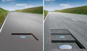
The pulse induction technology leads to a high noise immunity and a wide measurement range. Probe head and electronic housing are connected through a take-apart central pipe.

A sensor field collects answering signals of metal reflectors. The analysis of the spatiotemporal gradient, which uses the methods of the electromagnetic tomography, avoids subjective measurement errors. A search mode allows for the very effective location of a reflector in a 2 m wide pavement corridor, while the device is moved on a meander shaped path at 10 cm above the road surface. The presence of a reflector is shown as well on the display as through an acoustic signal. Immediately after the measurement, the results are displayed.

Videos

Asphalt Thickness and Concrete Thickness Test – NDT – MIT-SCAN-T3

Documents

Category

Topic

Publication Date

Measurement of asphalt thickness

Author: Iain McIver, Richard Jackett

Date: 30 June 2020

Pavement Thickness California DOT TO 09_FINAL_Report_082707wsig

Date: August 2007

Pavement Thickness MIT SCAN T2 Jagan Finding & Cost Comparison FHWA Mobile Concrete Laboratory

Author: Jagan Gudimettla

TP D-StB 12 Technical Specifications For Determining Pavement Layer Thicknesses In Road Construction (Asphalt & Concrete Applications)

Florida DOT Comparison of Methods for Concrete Pavement Thickness Measurement 022013 Construction Conference

Author: Abdenour Nazef

Date: 19 February 2013

Method to Determine Pavement Thickness using Magnetic Tomography Technology – March 2007 – California Department of Transportation (Concrete Application)

Date: March 2007

MIT-SCAN-T2 Summary Presentation

Description of the Measuring Method MIT SCAN T3 042016

Date: April 2016

Determination of Using the Magnetic Imaging Tomography Technique – TechBrief Concrete Sept 2009

Date: September 2009

Brochures

Brochure MIT-SCAN-T3 Layer Thickness Test for Asphalt Concrete and Unbound Materials

Blogs

One of our innovative clients, WSP, was looking for a way to assess the thickness of asphalt layers during the construction process and easily report their findings. They wanted to do this non-destructively and in a manner that seamlessly integrated with the construction process. These requirements and the accuracy needed led them to the MIT-SCAN-T3, an […]

Credentials

The MIT-SCAN-T3 product is used by organisations in the following categories:

  • Road Construction companies
  • Geotechnical Testing specialists
  • Road and Transport Authorities
  • Universities and Research Institutions

To find out more, Contact Us.

The MIT-SCAN-T3 is manufactured in Germany by MIT Mess- und Prüftechnik GmbH. MIT stands for Magnetic Imaging Tools. Over 400 units have been sold and the MIT-SCAN-T3 has been in production since 2005.

MIT Mess- und Prüftechnik GmbH
Gostritzer Str. 61-63, D-01217 Dresden, Germany
www.mit-dresden.de

Trusted by our clients

Our Supply Partners:

Insitutek Blogs

We find clients are often looking for ways to improve geotechnical testing outcomes and do it more efficiently at the same time. This drives their buying decision making. Australian Soil and Concrete Testing (ASCT) was a case in point when they were searching for Plate Load Test equipment for their upcoming Collector Wind Farm project. Some of the things that motivated them include: […]

We are excited to introduce the addition of a new Liquefaction Risk Estimation module in WebSprint©. Paired with our cutting-edge products, PANDA® and GRIZZLY®, this module enables you to assess the liquefaction risk of soils exposed to seismic stress. PANDA® Instrumented DCP: This cutting-edge tool provides dynamic penetrometer soundings, delivering precise data crucial for seismic risk evaluations. GRIZZLY® […]

The Australian Geomechanics Society is gearing up for a series of geotechnical events across VIC, WA, NSW, and SA-NT. We are thrilled to inform you that we will be sponsoring and attending these exciting geotechnical events, and we would love for you to join us. It’s a fantastic opportunity to catch up, explore our booth (VIC), and stay informed about […]