By providing reliable geotechnical data for rail formation and ballast condition assessment, our innovative testing methods enable rail asset managers / infrastructure managers to optimise the track maintenance and track renewal strategy by prioritising and allocating rehabilitation efforts and funding only to the sections that require priority attention whilst minimising track downtime. Their objectives maybe:
- Maintain the current usage requirements
- Accommodate increases in safety, train frequency, speed and load
The main functions of railway ballast are:
- to provide high load bearing capacity which reduces pressure from the sleeper bearing area to acceptable levels at the surface of the subgrade soil
- to provide rapid drainage
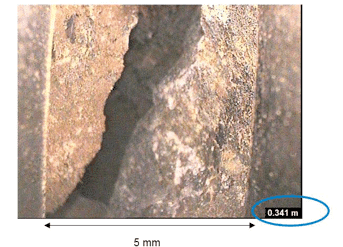
Rail ballast usually contains uniformly graded material creating a sufficiently large pore structure to facilitate rapid (free) drainage. When ballast is aged and degraded, fine particles accumulate within the voids (fouling) thus impeding drainage. The process of ballast fouling, when it becomes extreme, can also generate excess pore water pressure under fast moving trains (i.e., high cyclic loading), thereby reducing the track resiliency and stability (undrained).
The maintenance costs of ballasted tracks can be significantly reduced if an accurate estimation of the different types and degree of fouling materials can be related to track drainage.
Our innovative testing methods provide both mechanical and physical properties of the existing ballast and formation (subgrade and sub ballast layers) – both very important for future planning and track design. They enable you to assess:
- Performance under loading (modulus) – using tools including the Light Weight Deflectometer and Plate Load Test, we are able to simulate insitu how the track will perform under the dynamic loadings applied on passenger, freight or heavy haul rail networks. This can be informative for both planning track maintenance and rehabilitation works and during new construction, maintenance and rehabilitation works. There is also the possibility to assess California Bearing Capacity (CBR) insitu, using Dynamic CBR.
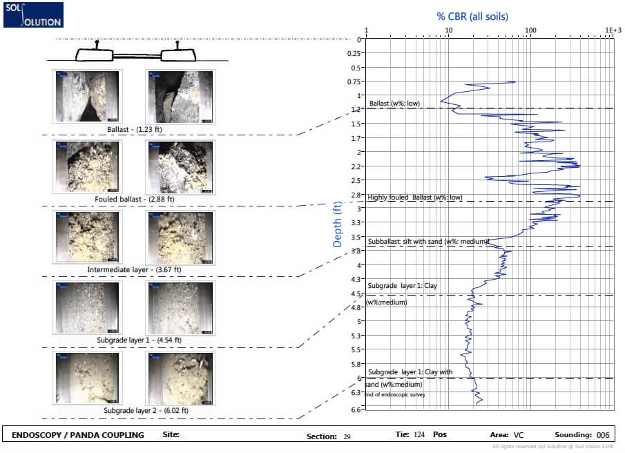
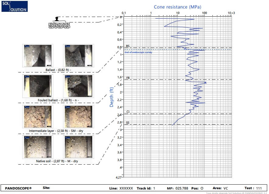
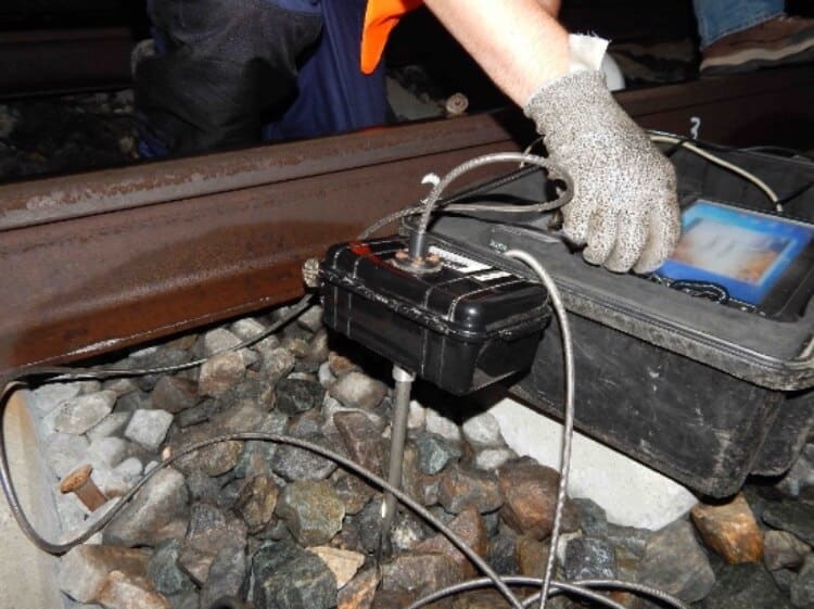
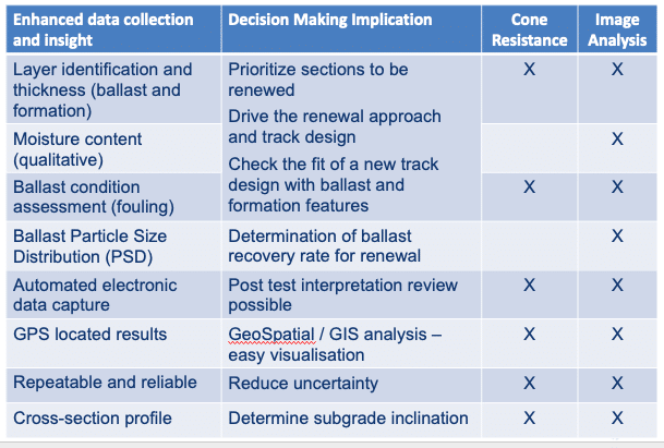
- Ballast and formation condition assessment – our PANDOSCOPE® method, a coupling of tip resistance vs depth profile with down the hole imagery is used for non-destructive rail track ballast assessment (ballast fouling) and condition monitoring of the formation (rail track substructure layers). To be more specific, the PANDOSCOPE® allows layer characterisation for ballast and formation (identification, thickness, water content (qualitative), estimation of the soil grain size distribution and ballast condition (ballast fouling) assessment. Cone resistance values can be correlated with CBR or other geotechnical parameters.
PANDOSCOPE® testing and GRIZZLY DPSH and push tube sampling are also used to calibrate Ground Penetrating Radar (GPR) data and to provide more information in problem areas.
To find out more, Contact Us.