Non Destructive Thickness Measurement Of Asphalt Layers – A New Zealand Case Study
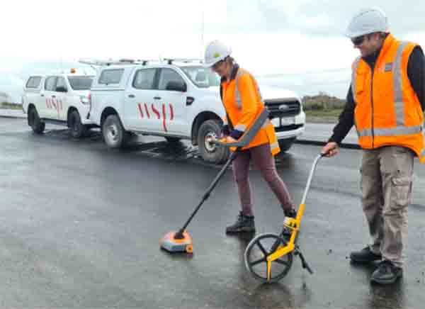
One of our innovative clients, WSP, was looking for a way to assess the thickness of asphalt layers during the construction process and easily report their findings. They wanted to do this non-destructively and in a manner that seamlessly integrated with the construction process.
These requirements and the accuracy needed led them to the MIT-SCAN-T3, an NDT device.
- Accuracy of the MIT SCAN is ± (0.5% of measured thickness + 1mm).
The project was a 12 km long 4 lane expressway with a structural asphalt pavement. WSP’s role was acting as the client representative, for the Waka Kotahi NZ Transport Agency, ensuring complying quality was being achieved.
The MIT-SCAN-T3 uses reflectors inserted into the pavement during construction, hence the test is only suitable for situations where reflectors can be inserted into the pavement during the construction process.
In this case, WSP used both the 300mm and 120mm diameter aluminium reflectors. This gave them more flexibility with regard to when they were able to access the site.

The pavement structure was made up of the following:

Ideally, where they could get in early enough, they placed the 300mm diameter reflectors and measured the three successive layers of asphalt. The finish of the stabilised AP65 subbase was often uneven and made attaching the 300mm diameter reflectors difficult. Occasionally construction activities dislodged some of the reflectors before they could be paved over. WSP designed and 3D printed dowels that were glued to the bottom of the reflector and anchor fixed into the stabilised granular pavement. This significantly reduced the amount of glue required to hold the reflectors and almost completely eliminated the loss of reflectors caused by construction activities.

Figure 1 – 300mm reflector with the 3D printed dowel attached
WSP have since found a supply of off the shelf dowels and are currently using the larger of the two shown in the photograph below.

Figure 2 – Commercially available dowels
In section across the pavement, the initial thinking was to place reflectors in the middle and outer edges of each paving run. With reflectors placed at 40m cross section intervals it was too difficult to place and maintain seven reflectors so the layout was changed to placing a reflector near the middle of each run reducing the number of reflectors to three for each cross section. The general layout configuration is shown in the following diagram.

In the locations where the 300mm reflectors were dislodged, WSP used the 120mm diameter reflectors, placed on top of the AC20 layer and were able to measure the thickness of the AC14 layer and then the Epoxy Modified Open Graded Porous Asphalt (EMOGPA) wearing surface.
To provide greater coverage of the EMOGPA wearing surface thickness, 70mm reflectors were placed on top of the AC14 on cross-sections between the 300mm reflectors. This provided thickness measurements at 20m intervals.
The MIT-SCAN-T3 enables the quick location of the reflectors and then, the GPS located time stamped asphalt thickness reading is taken and recorded electronically. Data is transferred to the phone or tablet based MIT-SCAN-T3-APP, which enables you to:
- Review the current measurements
- Manage your measurement data
- Create and send reports
Data can also be transferred to the PC-based MIT-Project-Software for data storage, presentation and geo-positioning of results.

The benefit of using the MIT-SCAN-T3 compared with traditional layer thickness measurement is that a very comprehensive coverage of asphalt thickness can be produced without cutting any core holes in the asphalt.
Cores may need to be cut to measure air void compliance in the asphalt, but if calibrated Nuclear Density Meter (NDM) thin lift gauge results are acceptable, or there is not a requirement to measure air voids, then there is no need to complete any destructive compliance measurements.
Other significant benefits of using the MIT-SCAN-T3 is the saving in time, personnel, and equipment to compile the layer thickness results.
Time is saved as the scanning can be completed as soon as the asphalt is sufficiently cool to run the MIT-SCAN-T3 over the surface. There is no need to wait until the asphalt is sufficiently cold enough to core.
The personnel saving is that the scanning can be completed quickly and efficiently by one person using the MIT-SCAN-T3. Coring would take much longer and would generally require two Laboratory technicians to complete the coring safely.
The equipment saving is the simplicity of use and cost of the MIT-SCAN-T3 compared to the use and cost of a coring rig.
We are using the PANDITO DCP for Level 1 site supervision, it’s very portable and we find it handy for flying into sites.
After scouring the market, we settled on the PANDA DCP test equipment as it offered the technical capability and, moreover, the flexibility required to work in the restricted environment our project presented; overhead clearance typically at 1500mm but as low as 1200mm. We had a unique problem that required a unique solution and that’s precisely what we found through the team at Insitutek and the PANDA equipment. The ease of assembly, intuitive operability and compact nature of the equipment, made light of the numerous soundings we required across a widely dispersed area.
If your after sales service is anything like what I have already received, I think I definitely made the correct choice.
Insitutek Blogs
We find clients are often looking for ways to improve geotechnical testing outcomes and do it more efficiently at the same time. This drives their buying decision making. Australian Soil and Concrete Testing (ASCT) was a case in point when they were searching for Plate Load Test equipment for their upcoming Collector Wind Farm project. Some of the things that motivated them include: […]
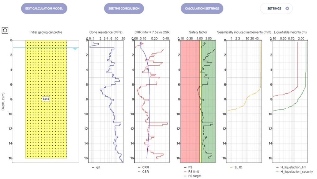
We are excited to introduce the addition of a new Liquefaction Risk Estimation module in WebSprint©. Paired with our cutting-edge products, PANDA® and GRIZZLY®, this module enables you to assess the liquefaction risk of soils exposed to seismic stress. PANDA® Instrumented DCP: This cutting-edge tool provides dynamic penetrometer soundings, delivering precise data crucial for seismic risk evaluations. GRIZZLY® […]
The Australian Geomechanics Society is gearing up for a series of geotechnical events across VIC, WA, NSW, and SA-NT. We are thrilled to inform you that we will be sponsoring and attending these exciting geotechnical events, and we would love for you to join us. It’s a fantastic opportunity to catch up, explore our booth (VIC), and stay informed about […]


