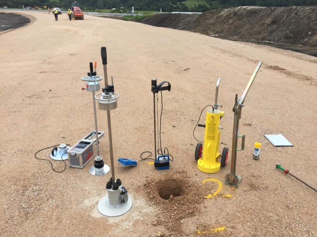
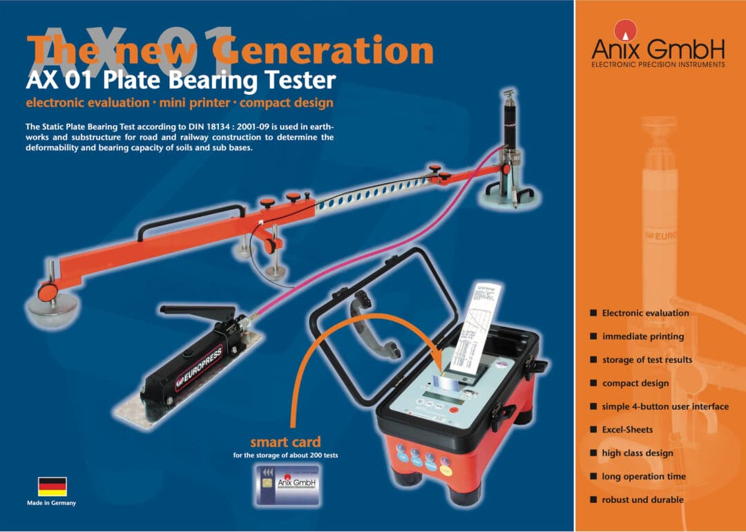
Plate Load Test / Plate Bearing Test
- Used to determine the allowable and ultimate bearing capacity
- Measures the load-deflection relationship
- Suitable for pavement, foundation and temporary works platform investigation.
- Immediate repeatable results so that on-site decisions can be made straight away
- Meets DIN 18134 and ASTM 1195 / ASTM 1196 standards
- Automatic operation – optional
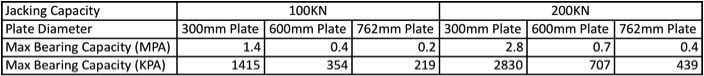
Bearing Capacity and Likely Settlement under Load
The Plate Load Test and is normally used to measure the short term settlement of pavement sub-grade, temporary works platforms or building footings under their proposed design load. The value of settlement against load is then used to check that the soil meets design load settlement criteria. The test therefore is of use to both contractors and to specifying authorities and is regarded as the ‘gold standard’ of insitu assessments.
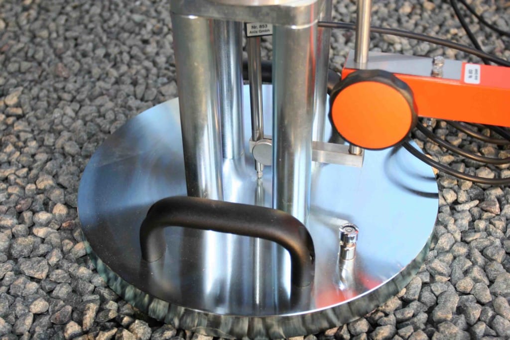
The AX01 Plate Load Test is used to determine:
- Load-settlement (deflection) curve
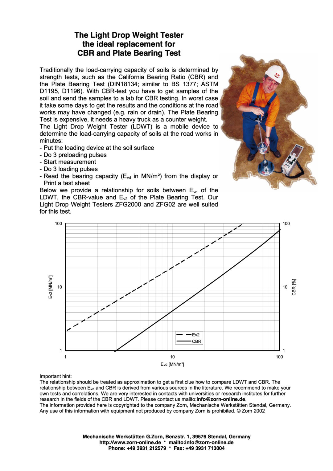
- Strain moduli of the first and the second loading cycle, Ev1 and Ev2 (an indicator for the bearing capacity of the soil under the loading plate)
- Modulus of subgrade reaction, ks (a measure of the stiffness)
- Ratio Ev2/Ev1 (a figure for the compaction level)
Site characterisation is unarguably the most important, but also most “difficult”, component of geo-engineering. The AX01 Plate Load Test is designed to improve the quality of site characterisation and reduce the difficulties involved.
The AX01 Plate Load Test from Anix GmbH is designed according to DIN 18134: 2012-04 and meets ASTM 1195 Standard Test Method for Repetitive Static Plate Tests of Soils and Flexible Pavement Components for Use in Evaluation and Design of Airport and Highway Pavements / ASTM 1196 Standard Test Method for Nonrepetitive Static Plate Tests of Soils and Flexible Pavement Components for Use in Evaluation and Design of Airport and Highway Pavements.
Compaction Control
The Plate Bearing Test measures a series of deflections (for a range of applied bearing pressures) and calculates a static modulus value for each of the loading cycles (Ev1 and Ev2). Modulus is the most accurate and independent means for judging deformation (stiffness) and, thus, a material’s level of compaction.
By measuring the modulus value, the Plate Load Test provides the direct link between the design specification (typically resilient modulus Mr) and the actual site condition (in-situ modulus value).
Check out the latest research on alternatives to the traditional density approach to compaction.
Plate Load Test Advantages
The advantages of the AX01 Plate Load Test include:
- Measuring actual foundation performance:
- Reduce construction risk as design assumptions / parameters are directly validated
- Increase certainty of design assumptions (reduces the risk of over design and under design)
- Potential to refine design parameters based on on-site measurements – potentially reducing capital cost
- Option to change loading hold times, depending on client requirements
- Option to change loading and unloading increments, depending on client requirements
- Faster
- Short operation time (approx 25-30 mins per test including setup, test & results graphing), rather than 2-4 hours just to setup and do the test plus data analysis adding significant additional time
- Provides immediate results so that on-site decisions can be made straight away.
- Cost effective
- One person operation
- Automatic operation – optional
- Improved safety
- Safe operation as operator away from the counterweight and does not read dial gauges and record results whilst under the counterweight
- Accurate and Repeatable
- Results directly reflect insitu site conditions
- Non destructive
- Without errors
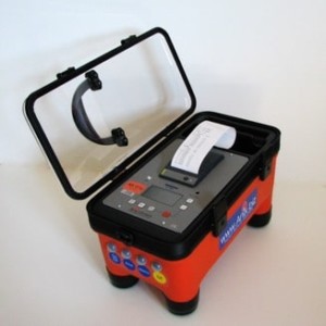
- No further data analysis or calculations required – data is analysed electronically on the spot, saving significant time
- Equipment is instrumented (data is automatically and accurately recorded)
- Results are machine produced (overcoming manual data recording, transposition or calculation errors and fictitious results)
- Improved data flow and integrity
- GPS located and time stamped – know where and when every test is done
- Visually presented results
- Graphical representation of the data on the electronic box
Plate Load Test Applications
Applications for this non destructive plate bearing test method for measuring bearing capacity and compaction control include flexible pavements, unsealed roads and mine access roads, tunnels, railway track beds, airport runway and taxiways, hard standing areas, wind farms, building foundations, pipe laying and tank farms.
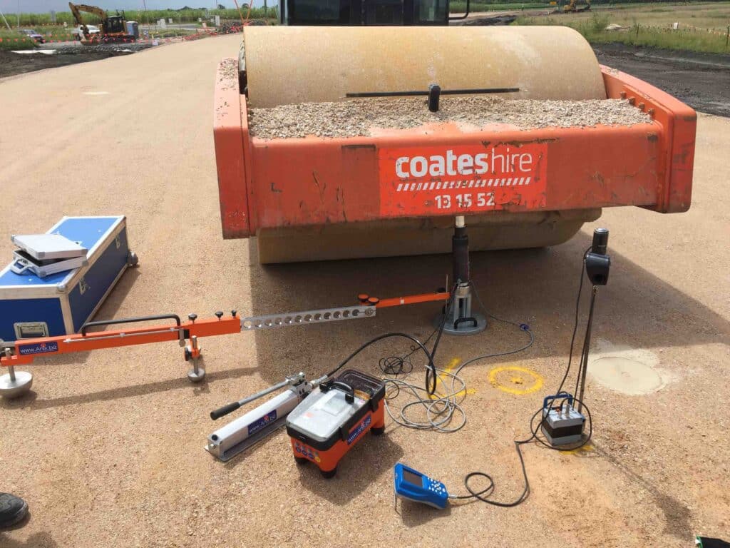
For example, the Plate Load Test is used to determine whether the ground has sufficient bearing capacity to support a given structure such as temporary pads for crane outriggers or piling rigs. It is very useful for mobile crane operators and piling rig contractors to check potential settlement of crane pads or mats under full load before the mobile crane or piling rig is sited or when traversing the site. The results of a Plate Load Test will enable you to calculate the size of outrigger spreader plates or mats required, and the ground movement that can be expected.
We also have clients who require bearing capacity data but no penetration is allowed because of services e.g. on railway trackbeds.
Clients include those involved in pavement construction, pavement rehabilitation, material testing, geotechnical testing and site investigation and include road authorities, councils, asset managers, mines, engineering and construction groups, mobile crane operators and piling rig contractors, geotechnical consultancies and research organisations.
Plate Load Test (PLT) Calibration, Service and Spare Parts
Insitutek are proud to represent Anix GmbH AX01 Plate Load Test (PLT) equipment in Australia, New Zealand and the Pacific Islands and provide a very high level of client support.
We offer a complete spectrum of services including after-sale technical support, servicing, repairs, and calibrations. Our service centre is also well stocked with spare parts and consumables.
To find out more, Contact Us


 The
The 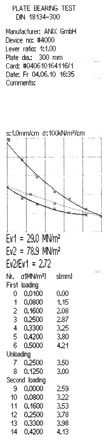


")